
Chapter 5: Design for Manufacture and Assembly Best Practices
In the Chapter 2 case study, we learned that the most effective implementations of DFMA start at the product design state and use a concurrent engineering approach to simplify the design both in part quantity and costs for manufacture and assembly. Simplification introduces the concepts of design elegance with a focus on the attributes of manufacturability, including:
- Part count reduction
- Ease of part handling at the point of assembly
- Ease of part insertion into the assembly
- Minimal use of tools (if any)
- Minimal use of standard or special processing
You will see many additional best practices are included in this chapter. These are truly a starting point, as all industries continue to evolve and improve. When designing a product, sue these general guidelines to guide the DFMA process and always take the time to research and incorporate the current industrial best practices which are appropriate.
Review
Before moving on, please review this article from Chapter 2 on How to Manufacture Success. After you’ve read the article, review the following slides and answer the check your understanding questions.
It all sounds so simple, right? Each of these topics can require significant research and application of DFMA tools. In this chapter, we will expand on these topics to better support implementation of the DFMA process.
Reducing Part Count
How can we determine which parts are necessary and which parts can be eliminated? Conduct a DFMA functional analysis to determine what parts are essential and what parts could be eliminated.
Theoretical Part Count
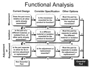
Below is a functional analysis flow chart. The flow chart evaluates the current design on movement, isolation, and a final category related to service, adjustment, and replacement. The questions require the evaluator to consider the current design of an element, specifications, and potentially other options. If, when evaluating, the answers to all of the questions are yes, then the part is considered essential. Otherwise, there may be a way to design the product without the part. The number of essential parts identified determines the number of minimum parts, which is called the theoretical part count. The functional analysis defines the theoretical part count, but there are some practical considerations to be made; for example: what are some potential risks for eliminating all fasteners?
Theoretical Minimum Part Count Guidelines
- One base part is always essential.
- Additional parts are considered non-essential until proven otherwise by the questionnaire
- Multiples of fasteners are always considered non-essential. Challenge whether a fastener is needed at all.
- Processes for coatings, finishing, adhesives, or lubricants should be captured in the analysis.
- Just because a part is in an assembly, moves independently, is made of a different materials, previous required (and so on), does not mean it still should be; the goal is to challenge the existing design with new creative ideas.
- The minimum part count is rarely ever fully achievable, it is a goal given the current functionality requirements. The final design will be measured against the goal.
Practical Part Count
Simplify Manufacture and Assemble
Research Off-The-Shelf (OTS) Parts
“Anderson’s Law -Never design a part you can buy out of a catalog unless you can clearly justify the choice (e.g. to save weight (if that’s an important design goal), to reduce size for improved packaging, to use an alternate material, etc.). Off-the-shelf (OTS) parts are significantly less expensive considering the cost of design, documentation, prototyping, testing, improving and the overhead cost of purchasing all the constituent parts. Suppliers of off-the-shelf parts are more efficient at their specialty because they are more experienced on their products, continuously improve quality, have proven reliability records, design parts better for DFM and have dedicated production facilities that can produce parts at lower cost (it’s difficult to compete on the price of twenty parts with a company that manufactures the same part by the thousands). Using OTS parts helps us focus on our real mission: designing and building products.”(From University of Florida)
Understand Process Limitations
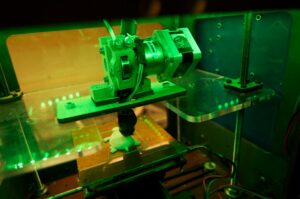 When designing a product, an understanding of the manufacturing processes is critical. For example, an Injection Mold manufacturing process is very different from an additive manufacturing process such as 3D printing. The machine and tooling/die costs, time to process, limitations in part geometry which can be created, and dimensional tolerances that can be achieved are very different. While it is sometimes a chicken or the egg challenge to determine which comes first—the part design and the manufacturing process decisions greatly impact one another. Often a manufacturer already possesses standard equipment, and the engineer is designing product to be produced on the established equipment.
Document Product and Process Limitations
Use Modular Design Principles
Designing families of products that use similar components drastically reduces the demands on manufacturing and overall cost to produce.
Ease of Part Handling at the Point of Assembly
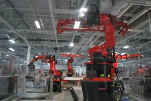 While it is understandable that every component will have time and cost associated with for the actual assembly process, we often overlook the fact that these components must be picked up and oriented properly before installation. This is true regardless of whether the component is manually assembled or assembled with the assistance of automation equipment. However, the increasing use of automation in manufacturing processes has highlighted the need to design components for ease of handling and orientation. Imagine for instance, a robot picking up a steel ball for assembly. While it may be challenging to grab just one, the symmetry eliminates the need for orientation. If the part were instead a gear, the part geometry would require more time to properly orient it before assembly. Design Engineers can dramatically reduce the cost for part handling and orientation by incorporating some design best practices.
Part Symmetry
Additional Concepts for Easing Part Handling
- Part Size: Very large and Very small parts create challenges for handling often requiring assistive tools like fork trucks, lifts, or tweezers. Additional tools add cost to the process and also typically increase the handling time.
- Reduce Nesting: Nesting is created when parts get tangled or joined together in storage making it difficult to separate individual units. Paper clips are an excellent example of parts which nest very easily. Thought should be given to how the parts will be packaged both from a supplier and between manufacturing processes and efforts should be taken in the part and packaging design to avoid nesting.
- Reduce Sharps/Hazards: Any part which creates a potential safety risk during handling will require additional time and possibly equipment for handling. Consider the assembly of a exacto blade compared to a similar sized ink pen. One blade must be removed from the supply of blades and then assembled into a knife handle to create a finished exacto blade. This would require more time and care than assembling the ink tube into a pen case.
Minimal Use of Fasteners and Tools (if any)
 While tools and automation are often added to improve manufacturing, the goal in the product design is to minimize the need for tooling. For instance, a snap fit case requires no tooling and is much faster to assemble than a threaded fastener which requires a tool.
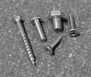
If fasteners have to be used, then some guides should be followed for selecting them. For more details, select the following link for information from University of Minnesota: Design for Manufacturing
- Minimize the number, size, and variation used.
- Utilize standard components whenever possible.
- Avoid screws that are too long, too short, separate washers, tapped holes, round/flathead screws (not good for vacuum pickup).
- Self-tapping and chamfered screws are preferred because the improve placement success.
- Screws with vertical side heads should be selected due to vacuum pickup.
Ease of Part Insertion into the Assembly
 Design for a base part to locate other components.
- Emphasize Top-Down assemblies: The part can be all assembled from one orientation without needing to re-orient. Tools such as drills, screw guns, and so on can all be used from above and not from other angles including from underneath the base part.
- Considering the current insertion (locate and secure) technique: based on difficulty required for each component insertion.
- Is the part secured immediately upon insertion?
- Is it necessary to hold down part to maintain location?
- Is the part easy to align/position?
- Part insertion considerations
- Self-aligning parts
- Self-locating parts
- Adequate access and visibility
- One-way orientation
- Avoid reorientation during assembly
Incorporate Mistake Proofing (Poka-Yoke)
- Integrate where needed to avoid quality errors or safety hazards.
- Design in mistake-proofing into assembly to prevent wrong parts being assembled, parts being omitted, and assembling parts in the wrong orientation. Examples include using bsses, tapers, locating holes, part symmetry, and part asymmetry.
Minimal Use of Standard or Special Processing
If possible, avoid the use of special coatings, treatments, finishing, handling, machining operations etc. Whenever possible, evaluate the design for alternatives which would reduce this extra cost and processing which could also lead to quality errors.
